Designing
the full-state feedback controller
Adding a
reference input
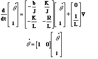
From the main problem, the dynamic equations in state-space form are the following:
With a 1 rad/sec reference added to the system, the design criteria are:
Designing
the full-state feedback controller
Adding a
reference input
From the main problem, the dynamic equations in state-space form are the following:

With a 1 rad/sec reference added to the system, the design criteria are:
Create a new m-file and type in the following commands (refer to the main problem for the details of getting these commands).
J=0.01;
b=0.1;
K=0.01;
R=1;
L=0.5;
A=[-b/J   K/J
   -K/L   -R/L];
B=[0
   1/L];
C=[1   0];
D=0;
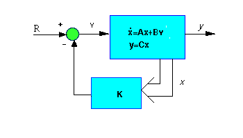
Since both of the state variables in our problem are very easy to measure (simply add an ammeter for current and a tachometer for the speed), we can design a full-state feedback controller for the system without worrying about having to add an observer. The schematic for a full-state feedback system is:
p1 = -5 + i;
p2 = -5 - i;
K = place(A,B,[p1 p2]);
Now look at the schematic above again. We see that after adding the K matrix into the system, the state-space equations become:

t=0:0.01:3;
step(A-B*K,B,C,D,1,t)
Run your m-file in the command window, You should see the following plot:
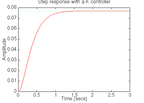
From this plot we see that the steady-state error is too large. In contrast to the other design methods, where we feed back the output and compare it to the reference to compute an error, here we are feeding back both states. We need to compute what the steady-state value of the states should be, multiply that by the chosen gain K, and use this new value as our reference for computing the input. This can be done in one step by adding a constant gain Nbar after the reference:
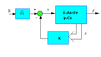
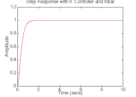
Nbar=rscale(A,B,C,D,K)Note that the function rscale is not a standard function in Matlab. You will have to copy it before you use it. Now we can plot the step response by adding the following line of code to your m-file:
t=0:0.01:10;
step(A-B*K,B*Nbar,C,D,1,t)
title('Step Response with K Controller and Nbar')
