Proportional
control
PID
control
Tuning
the gains
From the main problem, the dynamic equations in transfer function form
are the following:

and the system schematic looks like:
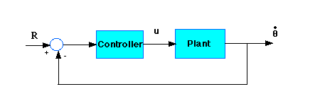
With a 1 rad/sec step reference, the design criteria are:
Proportional
control
PID
control
Tuning
the gains
From the main problem, the dynamic equations in transfer function form
are the following:

and the system schematic looks like:

With a 1 rad/sec step reference, the design criteria are:
Now let's design a PID controller and add it into the system. First create a new m-file and type in the following commands(refer to main problem for the details of getting those commands).
J=3.2284E-6;
b=3.5077E-6;
K=0.0274;
R=4;
L=2.75E-6;
num=K;
den=[(J*L) ((J*R)+(L*b)) ((b*R)+K^2) 0];
Recall that the transfer function for a PID controller is:

Let's first try using a proportional controller with a gain of 1.7. Add the following code to the end of your m-file:
Kp=1.7;
numcf=[Kp];
dencf=[1];
numf=conv(numcf,num);
denf=conv(dencf,den);
To determine the closed-loop transfer function, we use the cloop command. Add the following line to your m-file:
[numc,denc]=cloop(numf,denf);Note that numc and denc are the numerator and the denominator of the overall closed-loop transfer function.
Now let's see how the step response looks. Add the following to the end of your m-file, and run it in the command window:
t=0:0.001:0.2;
step(numc,denc,t)
You should get the following plot:

Now lets take a look at the step disturbance response. Add the following to the end of your m-file, and run it in the command window:
numdcl=conv(numc,1);
dendcl=conv(denc,Kp);
step(numdcl,dendcl,t);
You should get the following plot:
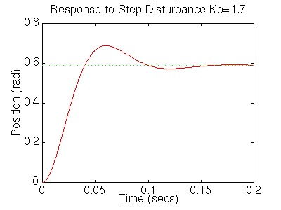
From the plots above we see that although the steady-state error looks good the settling time is too large, as is the overshoot. We also see that the steady-state error to a disturbance is large. Add an integral term will eliminate the steady-state error and a derivative term will reduce the overshoot. Let's first try a PI controller to get rid of the disturbance steady state error. Change your m-file so it looks like:
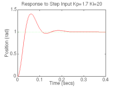
Lets see what happened to the step disturbance response, add the following to your m-file:
figure
numdcl=conv(numc,dencf);
dendcl=conv(denc,numcf);
step(numdcl,dendcl,t);
You should get the following plot:
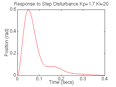
The settling time is still too long. Let's increase the gains in order to speed up the response. Go back to your m-file and change Ki to 200 and Kp to 17. Rerun the file and you should get plots like these:
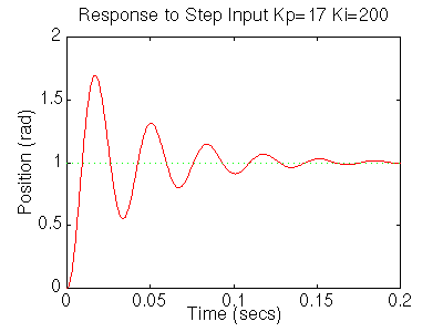
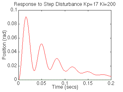
Now we see that the response is faster than before, but the large Ki has worsened the transient response (big overshoot). Let's now try a PID controller to reduce the overshoot. Go back to the m-file and make the following changes to look at the step response.
Kp=17;
Ki=200;
Kd=0.15;
numcf=[Kd Kp Ki];
dencf=[1 0];
numf=conv(numcf,num);
denf=conv(dencf,den);
[numc,denc]=cloop(numf,denf,-1);
t=0:0.001:0.1;
step(numc,denc,t)
Rerun it and you should get this plot:
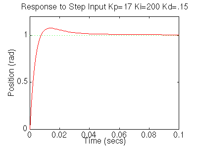
Your step disturbance plot should look like this:
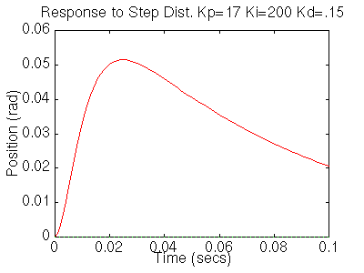
We now see that our step response looks really good, it has less than 16% overshoot and the settling time is roughly 40ms, and there is no steady-state error. However the step disturbance response is now really slow. Lets increase Ki to speed up the disturbance response. Change Ki to 600 in your m-file and rerun the file. You should get the following plots:
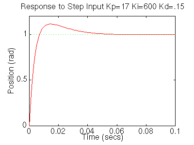
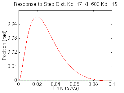
We now can see that the step response has a settling time of roughly 40ms, it has less than 16% overshoot, and it has no steady state error. The step disturbance response also has no steady state error. So now we know that if we use a PID controller with
Kp=17,
Ki=600,
Kd=.15,
all of our design requirements will be satisfied.