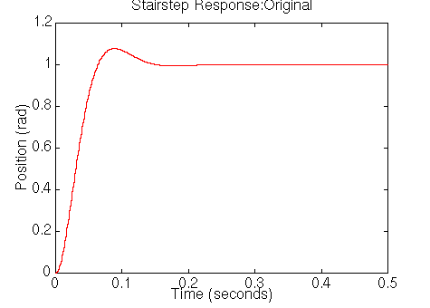
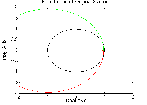
Ts: the settling time
The required damping ratio is 0.5 and the natural frequency is 200
rad/sec, but the zgrid command requires a non-dimensional
natural frequency. Therefore Wn = 200*T = 0.2 rad/sample. Add the following
Matlab code into the end of your m-file and rerun it.
rlocus(numad,denad);
zgrid(0.5,0.2)
title('Root Locus of system with integral control')
You should get the following plot:
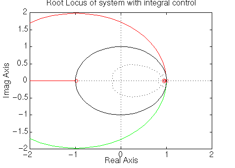
From the above root locus plot, we can see that system is unstable at all
gains because the root locus is outside the unit circle. Moreover, the root
locus should be in the region where the damping ratio line and natural frequency
cross each other to satisfy the design requirements. Thus we have to pull the
root locus in more by first canceling the zero at approximately -0.98, since
this zero will add overshoot to the step response. Then we have to add one more
pole and two zeroes near the desired poles. After going through some trial and
error to yield the root locus in the desired region, one more pole is added at
0.61 and two zeroes are added at 0.76. Add the following command in your m-file
and rerun it in Matlab window.
numc = conv([1 -0.76],[1 -0.76]);
denc = conv([1 0.98],[1 -0.61]);

numoc = conv(numad,numc);
denoc = conv(denad,denc);
rlocus(numoc,denoc);
zgrid(0.5,0.2)
title('Root Locus of Compensated System')
The denoc will have a pole at 0.61 instead of -0.98. You should get
the following root locus plot:
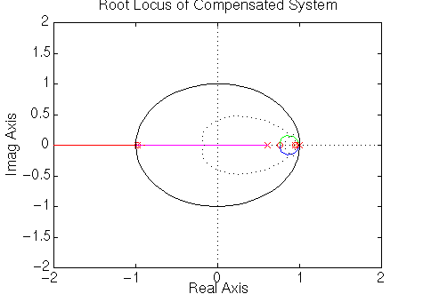
From the above root locus plot, the root locus is drawn in the desired
region. Let's find a gain, K, on the root locus plot by using the rlocfind command and obtain the stairstep response with the
selected gain. Enter the following commands at the end of your m-file and rerun
it.
K = rlocfind(numoc,denoc)
[numd_cl,dend_cl] = cloop(K*numoc,denoc);

[x2] = dstep(numd_cl,dend_cl,251);
t=0:0.001:0.25;
stairs(t,x2)
xlabel('Time (seconds)')
ylabel('Position (rad)')
title('Stairstep Response of Compensated System')
In the Matlab window, you should see the command asking you to select
the point on the root-locus plot. You should click on the plot as the following:
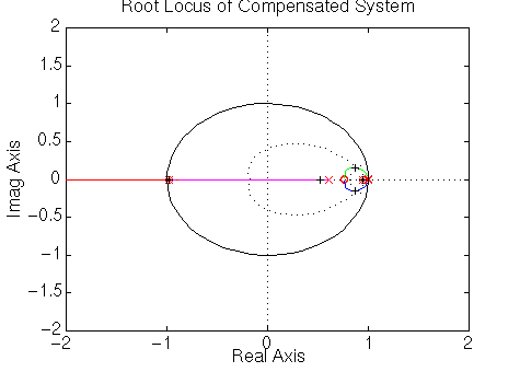
The selected gain should be around 330, and it will plot the closed-loop
compensated response as follows.
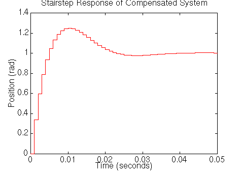
From the above closed-loop response, the settling time is about 0.05 seconds
which is satisfy the requirement, but the percent overshoot is 22% which is too
large due to the zeroes. If we select the gain to be larger, the requirements
will be satisfied. On the other hand, the problem will be unrealistic and a huge
actuator is needed, you can try this yourself by picking a larger gain on the
previous root locus plot which will yield an unrealistically sudden step
response. So we have to move both one pole and two zeroes a little further to
the right to pull root locus in a little bit more, new pole will be put at 0.7
and two zeroes should be at 0.85. Go back to your m-file and change only
numc and denc as shown below and rerun it in Matlab window.
numc = conv([1 -0.85],[1 -0.85]);
denc = conv([1 0.98],[1 -0.7]);
Then you should see the following root locus plot.
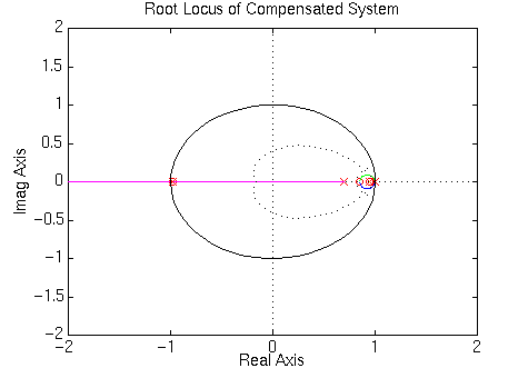
On the new root locus, you should click on the plot to select a new gain as
the following:
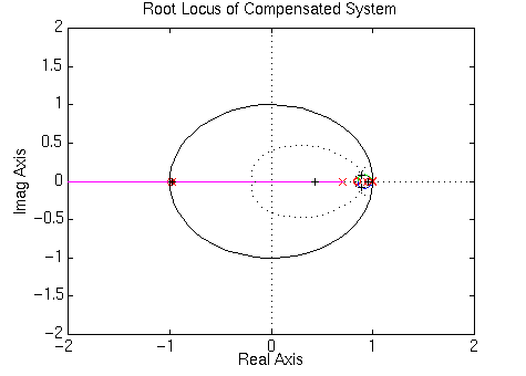
The selected gain should be around 450, and then it will plot the closed-loop
compensated response as follows:
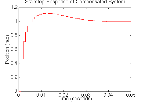
Now we see that the settling time and percent overshoot meet the design
require ments of the system. The settling time is 0.04 seconds and the percent
overshoot is about 10%.
Then let's take a look at a disturbance response of the closed-loop system by
canceling the selected gain, the integral transfer function and controller's
transfer function from the closed-loop transfer function. So add the following
code into your m-file and rerun it.
numcld = conv(numd_cl,conv(denc,deni));
dencld = conv(dend_cl,conv(K*numc,numi));

[x4] = dstep(numcld,dencld,251);
t=0:0.001:.25;
stairs(t,x4)
xlabel('Time (seconds)')
ylabel('Position (rad)')
title('Stairstep Response of Compensated System')
Matlab should return the following plot:
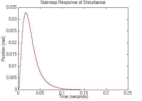
We can see that a response to the disturbance is small (3.3% of the
disturbance ) and settles within 2% of the disturbance after 0.04 seconds and
eventually reaches zero.
[ Table des matières ]

 to discrete transfer function by using the c2dm command.
The c2dm command requires four arguments: the numerator
polynomial (num), the denominator polynomial (den), a sampling time (T) and a
type of hold circuit. In this example we will use the zero-order hold (zoh).

