Proportional
control
PI
control
PID
control
The transfer function for this cruise control problem is the following,

Proportional
control
PI
control
PID
control
The transfer function for this cruise control problem is the following,

and the block diagram of an typical unity feedback system is shown below.

The design criteria for this problem are:
>The transfer function of a PID controller is

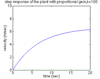
The first thing to do in this problem is to find a closed-loop transfer function with a proportional control (Kp) added. By reducing the block diagram, the closed-loop transfer function with a proportional controller becomes:


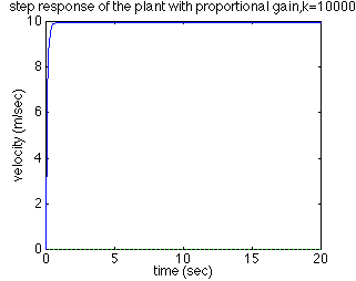
The steady-state error has dropped to near zero and the rise time has decreased to less than 0.5 second. However, this response is unrealistic because a real cruise control system generally can not change the speed of the vehicle from 0 to 10 m/s in less than 0.5 second.
The solution to this problem is to choose a proportional gain (Kp) that will give a reasonable rise time, and add an integral controller to eliminate the steady-state error.
The closed-loop transfer function of this cruise control system with a PI controller is:

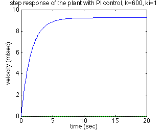
An addition of an integral controller to the system eliminates the steady-state error. For now, let Kp equals 600 and Ki equals 1 and see what happens to the response. Change your m-file to the following.

Now adjust both the proportional gain (Kp) and the integral gain (Ki) to obtain the desired response. When you adjust the integral gain (Ki), we suggest you to start with a small value since large (Ki) most likely unstabilize the response.
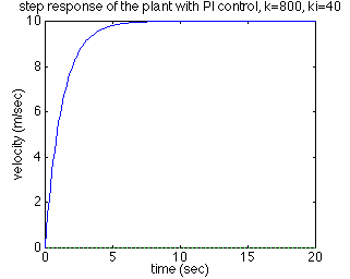
With Kp equals 800 and Ki equals 40, the step response will look like the following:

As you can see, this step response meets all design criteria.
For this particular example, no implementation of a derivative controller was needed to obtain a required output. However, you might want to see how to work with a PID control for the future reference. The closed-loop transfer function for this cruise control system with a PID controller is.

Let Kp equals 1, Ki equals 1, and Kd equals 1 and enter the following commands into an new m-file.
Running this m-file should give you the step response of the system with PID controller. Adjust all of Kp, Kd, and Ki until you obtain satisfactory results. We will leave this as an exercise for you to work on.
Suggestion: Usually choosing appropriate gains require trial and error processes. The best way to attack this tedious process is to adjust one variable (Kp, Kd, or Ki) at a time and observe how changing one variable influences the system output.